Key takeaways
- Five numbers decide the machine: thickness range, incoming coil width, coil inner/outer diameter and weight, narrowest strip, and width tolerance.
- Two standard configurations: SL-1250 (0.3–3.2 mm × 600–1250 mm, up to 12 t) and SL-1600 (0.35–4.0 mm, up to 1600 mm wide, up to 15 t).
- Width tolerance is documented at ±0.05 mm, and holding it depends on rigid knife shafts, levelling before slitting, and tension at the recoiler.
- A slitting line is a sequence of stations, not one machine — the edge trimmer and the tension station are part of the specification, not accessories.
- The finished width is set by spacers on the knife shafts, so the narrowest strip you must produce has to be stated before the line is quoted.
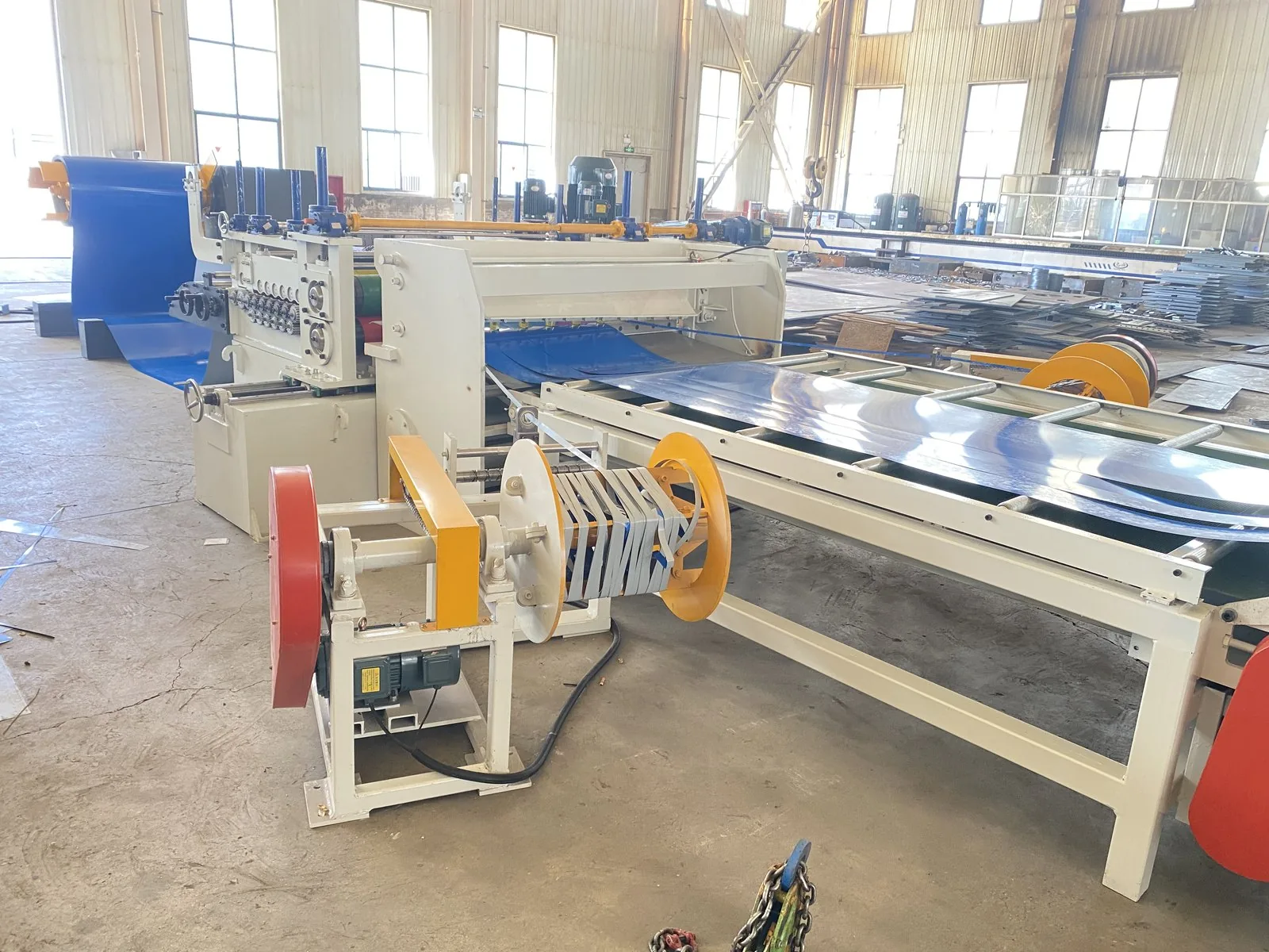
The five numbers that decide the line
A slitting line does one job: it takes a wide steel coil, cuts it into several narrow strips of a set width, then recoils them under tension. Almost everything about the machine follows from five numbers, and they are worth fixing before a quotation is requested.
Strip thickness range drives the knife shaft diameter, the motor power and the whole frame. Incoming coil width sets the maximum the line has to swallow. Coil inner diameter, outer diameter and weight size the decoiler mandrel and the recoiler. The narrowest strip you must produce sets the spacer and knife-disc design. Width tolerance is the acceptable deviation on the finished strip — on the lines we build it is documented at ±0.05 mm and verified on the finished strip.
Get these five right and the rest of the specification follows. Get them wrong and no amount of optional equipment recovers the line.
Two worked configurations
These are two standard configurations we build. They are useful because they show what a realistic specification looks like — and how the numbers move together.
| Parameter | SL-1250 | SL-1600 |
|---|---|---|
| Strip material | Cold-rolled, galvanised sheet | Galvanised, cold-rolled, hot-rolled coil |
| Strip thickness | 0.3–3.2 mm | 0.35–4.0 mm |
| Coil width | 600–1250 mm | up to 1600 mm |
| Coil inner diameter | Ø508 mm | Ø508 / 610 / 750 mm |
| Coil outer diameter | max 1600 mm | max 1600 mm |
| Coil weight | max 12 t | max 15 t |
| Coil camber | — | ≤2 mm/m |
| Slit strip width | from 20 mm | 30 mm on a second pass |
| Width tolerance | ±0.05 mm | ±0.05 mm |
| Line speed | max 25 m/min | threading 10 m/min; 10–20 m/min |
| Line footprint | — | 20 m × 8 m (L × W) |
Why ±0.05 mm is the number that decides the line
A width tolerance of ±0.05 mm sounds tight, and it is. It is achievable, but only when three things are right.
The knife shafts must be rigid enough — thin shafts deflect, and a deflecting shaft produces a taper cut. The strip must be levelled before it is slit: slitting a coil that still carries its coil set produces a curved strip, not a straight one. That is why the leveller sits in front of the slitting head — 17 rolls in a 7-over / 8-under arrangement plus one guide shaft, with Ø100 mm rolls in 40Cr, high-frequency hardened and hard chrome plated, and Ø90 mm support rolls on wedge adjustment so the levelling rolls do not bow under load. The recoiler must hold tension: without tension the strips wander and the widths drift.
If the downstream process is a tube mill or a roll forming line, tolerance is not cosmetic. Strip that is 0.1 mm over width at the edge feeds a different amount of material into the forming rolls, and the finished tube or profile drifts.
The components you are actually buying
A slitting line is not one machine, it is a sequence: hydraulic expanding-mandrel decoiler, a combined levelling / cut-to-length / slitting unit, edge trimmer (scrap winder — the trimmed edge has to go somewhere), tension station, recoiler, unloading car, hydraulic and pneumatic power unit, and the PLC electrical control system.
Two details are worth checking in any quotation. First, the decoiler mandrel. On the 1250 mm line it expands over 475–525 mm, which covers the common Ø508 mm coil bore, with a Ø194 mm main shaft, a 1250 mm effective mandrel length, a 7.5 kW centre drive and a Ø125 mm expanding cylinder working at 12 MPa. The 1600 mm line uses a single-head cantilever decoiler with an anti-loosening hold-down arm and a support arm, working up to 30 m/min and carrying coils from 2 t to 15 t. Second, the type of cut: these lines cut from the top down using twin hydraulic cylinders, which is a robust arrangement and is what makes the slitting head easy to set.
| Station | What to confirm in the quotation |
|---|---|
| Decoiler | Mandrel expansion range against your coil bore (475–525 mm covers Ø508 mm); coil weight capacity (12 t on SL-1250, 15 t on SL-1600); hold-down and support arms on cantilever designs |
| Leveller | Roll count and arrangement (17 rolls, 7 over / 8 under plus one guide shaft), roll material (40Cr, HF hardened, hard chrome plated), and support rolls to stop the rolls deflecting under load |
| Slitting head | Knife shaft diameter against the thickness range, number of knife sets, spacer system for width changes, and the rail base that gives access for knife changes |
| Edge trimmer | Whether edge scrap is wound automatically — trimmed edge is a station, not an accessory |
| Tension station and recoiler | Tension control type (hydraulic for heavier coils, pneumatic for lighter work) and the recoil bore |
| Control | Full-digital AC drives, PLC interlocks and fault alarms, presettable process parameters, and one console for the whole line |
Setting the slit width
The finished width is set by the spacer combination on the knife shafts, not by moving the knives. The head has a fixed frame and a movable frame; the movable frame travels on a rail base driven by an AC motor so the operator can reach the knife discs, spacers and shims, the upper knife shaft is raised by a worm gear and screw, and the depth of cut is fine-adjusted by hand.
This is why the narrowest strip you need must be stated. The SL-1250 is built to slit from 20 mm upwards, and the SL-1600 normally produces 2–5 strips from a 1600 mm coil with 11 knife sets (22 blades) available, taking strip down to 30 mm on a second pass. A line that only ever produces 400 mm strips from a 1250 mm coil is a different machine from one that has to produce 20 mm strips.
Electrical and control
Decoiler, leveller, shear and recoiler run on full-digital AC drives with the whole line under PLC control. The checks worth making: overload protection, circuit-breaker protection and emergency stop; line interlocks and fault alarms handled by the PLC; presettable process parameters; monitoring and alarms on key machine parameters; and a single console for shearing speed, coiling tension, length setting, single-machine adjustment and full-line automatic running.
Supply is commonly built as AC 380 V ±10 %, 50 Hz ±5 %, three-phase five-wire, with 0.4–0.6 MPa air. Export destinations frequently need something else, so it has to be specified up front rather than assumed.
Common specification mistakes
Quoting the line on thickness alone. Coil weight and coil bore often drive more of the cost than thickness does.
Forgetting the edge trim. Trimmed edge scrap has to be wound; it is a station, not an accessory.
Not stating the narrowest strip you must produce. The spacer and knife-disc design depends on it, and it cannot be added later without changing the head.
Assuming the line runs flat out at maximum speed all day. Threading speed and running speed are different numbers and are stated separately for a reason — on the SL-1600, 10 m/min threading against 10–20 m/min running.
Leaving supply voltage and frequency to the end. It is one of the few items that cannot be corrected after the control system is built.