Light Gauge Steel Framing Machine
Structural cold-formed steel sections for wall, floor and roof framing in prefabricated and mid-rise buildings — with optional swage for rapid site assembly.
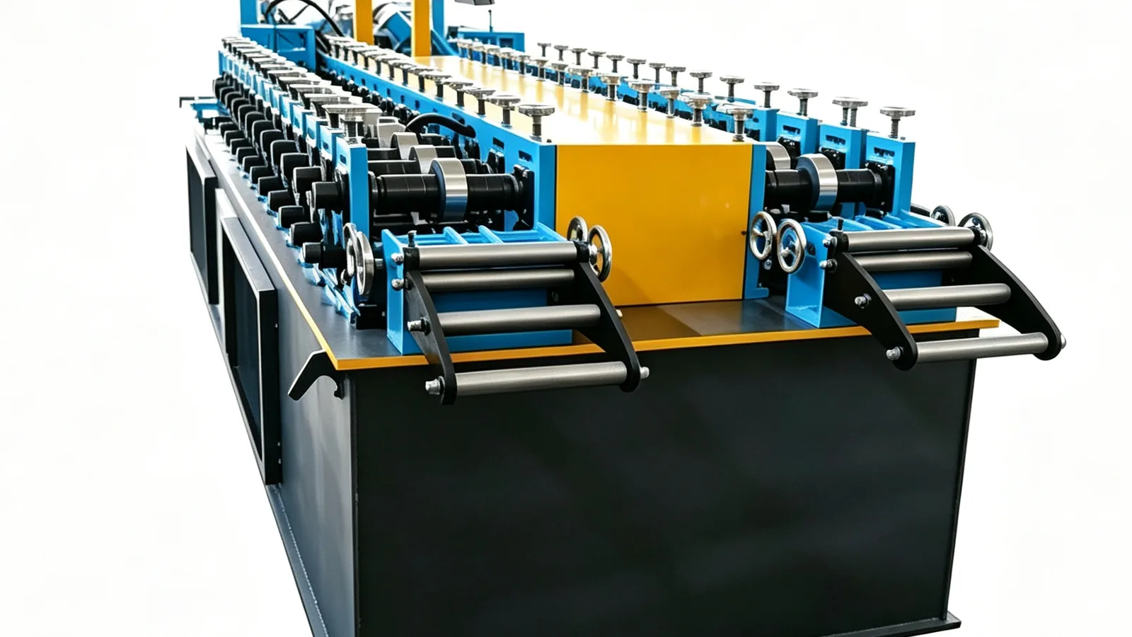
Technical Specifications
| Material | Galvanised steel, G250 – G550 |
| Thickness | 0.8 – 2.0 mm |
| Profiles | C-stud, U-track, floor joist, roof truss member |
| Web width | 70 – 300 mm |
| Forming speed | 10 – 25 m/min |
| Forming stations | 14 – 20 |
| Drive | Gearbox chain drive, 11 – 18.5 kW |
| Punching | Service holes and swage dimples, optional inline |
| Cutting | Hydraulic flying cut to length |
| Control | PLC + HMI, batch counter |
| Certification | CE Declaration of Conformity |
| Lead time | 45 – 60 days |
Need a quote or a custom specification?
What This Machine Produces
Structural C-stud sections in web widths from 70 to 300 mm — the primary load-bearing wall member in a light steel frame.
U-track in matching widths, for the head and base of every wall panel.
Floor joist members — deeper C sections in the same thickness range, used where a light steel floor deck is carried on cold-formed joists.
Roof truss members — the same C and U vocabulary used for roof framing in prefabricated light steel systems.
Swaged members — with the optional inline swage tooling, a raised dimple is formed so that a screw passes through a fixed-depth gap between nested studs, which speeds up site assembly and reduces the risk of over-driving screws.
Members cut and punched to a design list — where the optional design-software interface is fitted, the frame design outputs a cutting and punching list that feeds the machine control, so each member is produced automatically to the design.
Sections in 0.8–2.0 mm galvanised steel from G250 to G550, formed at 10–25 m/min.
Recommended Configuration
A complete working line, not just the forming machine. Each item below is quoted as one package.
- 01
Hydraulic decoiler and straightener
structural sections in 0.8–2.0 mm carry coil set into the finished member if it is not removed first, and a mis-straight frame member is rejected on site.
- 02
LGS roll forming machine
14–20 stations on a gearbox chain drive at 11–18.5 kW, running at 10–25 m/min.
- 03
Inline swage tooling (optional)
this is the unit that makes a light steel frame practical to assemble. Without it, every screw fixing point has to be aligned by hand.
- 04
Inline service-hole and dimple punch (optional)
punching the flat strip keeps service holes and fixing points consistently positioned along the member.
- 05
Design-software interface (optional)
accepts the cutting and punching list from LGS design software, which is the difference between running to a schedule and running to a drawing by hand.
- 06
Hydraulic flying cut to length with batch counter
frame members are many and short, so automated cut-to-list is what makes the line productive.
- 07
Runout table
long members need support along their length, not just at the cut.
Production Workflow
- 01
Decoiler
The coil is loaded and uncoiled at controlled tension. At 2.0 mm the coil is stiff enough that incorrect tension shows up as camber in the finished member.
- 02
Straightening
Coil set is removed before forming. On structural members this is not cosmetic: a member with residual bow will not close with the panel it is meant to receive.
- 03
Service-hole and dimple punching
When fitted, service holes and swage dimples are punched into the flat strip. Doing it flat is what keeps fixing points aligned along the member.
- 04
Roll forming
14–20 stations form the C-stud, U-track, floor joist or roof truss member progressively, in 0.8–2.0 mm galvanised steel at 10–25 m/min.
- 05
Swaging
Optional inline swage forms the raised dimple that sets the screw depth when two members nest, removing a site operation and a common source of over-driven screws.
- 06
Cutting and output
The hydraulic flying cut runs to length from the batch list, and members leave on the runout table in production sequence.
Key Components
- Forming stations
- 14–20
- Drive
- Gearbox chain drive, 11–18.5 kW
- Punching
- Service holes and swage dimples, optional inline
- Cutting
- Hydraulic flying cut to length
- Control
- PLC + HMI, batch counter; optional design-software interface
- Working range
- 0.8–2.0 mm steel, web width 70–300 mm
- Material grades
- G250–G550; G550 is standard for structural members
Customization Options
Every line is built to order. These are the points buyers most often change.
| Item | What can be changed |
|---|---|
| Profile schedule | C-stud, U-track, floor joist and roof truss member — tell us the full list so we can work out the minimum cassette count |
| Web width | 70–300 mm on the standard frame |
| Thickness and grade | 0.8–2.0 mm, G250–G550 depending on load and span |
| Coating | Z275 or AZ150 for corrosion resistance |
| Swage dimpling | Optional inline tooling for screw-fixed assembly |
| Design-software interface | Optional; feeds cutting and punching lists from LGS design software |
| Power supply | 380 V / 50 Hz / 3-phase standard; other voltages to your site |
Applications
FAQ — Light Gauge Steel Framing Machine
What is light gauge steel framing used for?
What is the difference between LGS framing and stud & track?
Does the machine include swage dimpling for screw fixing?
Can it produce both C and U sections?
What steel grade should be used?
Can the machine be fed by design software?
What is the typical output for a house frame?
Can the machine be built for our own profile?
How do we get a price for this line?
What is the production speed?
How many forming stations does it use?
What is the drive and installed power?
You May Also Need
Send us your profile and output target
Tell us the profile and the numbers that matter to you. We confirm the configuration against the specification table above and quote FOB Tianjin within 24 hours.
- MaterialGalvanised steel, G250 – G550
- Thickness0.8 – 2.0 mm
- ProfilesC-stud, U-track, floor joist, roof truss member
- Web width70 – 300 mm